|
|
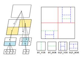
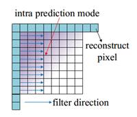
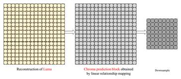
What is AVS3?AVS3 video coding standard is the the third generation standard developed by China AVS working group. It is designed to adapt multiple application scenarios, such as UHD TV broadcasting, VR and video surveillance. The development process of AVS3 is divided into two phases. The first phase aims to develop an software/hardware implementations friendly profile by adopting coding tools showing large coding gain with relatively limited complexity increment. So far, the first phase of AVS3 has been finalized in March, 2019, which achieves approximately a 30% bit-rate savings than AVS2 for 4K ultra-high-resolution videos. Moreover, more efficient coding tools for performance improvement and especial for surveillance videos and screen content videos are being developed in the second phase of AVS3. Key Coding Tools1. Block Partition AVS3 adopts a more flexible coding tree block partitioning scheme to support various resolution video contents well. The Coding Tree Unit (CTU) size in AVS3 can reach up to 128x128 and be partitioned into the least 4x4 blocks. As shown in Fig.1, based on the QT method, Binary-tree (BT) and Extend Quad-tree (EQT) are introduced into AVS3, and these split methods introduce non-square CU and provide sufficient flexibility for block partition. 2. Intra Prediction To predict different kinds of content efficiently, intra prediction filter (IPF) is introduced to eliminate the noise and get more accurate prediction samples. As the Fig.2 depicts, the IPF filter weighting is dependent on the position of prediction samples and block size. For chroma samples, as shown in Fig.3, a two-step cross-component prediction mode (TSCPM) was proposed to reduce the cross-component redundancy between the chroma and luma by predicting from the previously decoded luma samples.
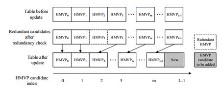
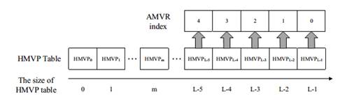
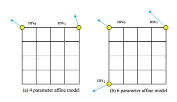
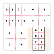
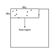
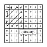
3. Inter Prediction For the skip/direct mode, a motion vector offset compensation method is proposed, called ultimate motion vector expression (UMVE), which can further refine the MV of skip/direct mode for better prediction. Moreover, a history based motion vector prediction (HMVP) method was adopted by using more previously coded blocks' motion information for prediction. The extension of skip/direct mode simplifies the block-wise motion data signaling significantly by inferring all motion data from already decoded blocks. To reduce the coding bits of motion vector difference (MVD), a CU level adaptive motion vector resolution (AMVR) scheme was developed, where the motion vector resolution can be selected from the set of {1/4, 2/1, 1, 2, 4} pixel denoted by motion resolution index. By reusing the AMVR index for motion vector prediction, an enhanced motion vector resolution (EMVR) mode is designed which can add more candidates for MV prediction coding. Apart from these, a subblock based motion vector prediction method, called affine prediction model was adopted, in which one CU is divided into the subblocks with equal size and the MV for each subblock is derived from control point MV. 4. Transform Some new type transform kernels include DCT-VIII, and DST- VII are introduced into AVS3 to get better energy compaction. The largest transform block size is extend to 64x64, which is efficient for large-flat block coding. A position based transform (PBT) technology is used where the different transform cores were selected according to the position of the block in the quad-tree partition. As shown in Fig.7, PBT splits the CU into four sub-blocks, each sub-block use pre-designed transform set according to their position. 5. Entropy Coding A scan region based coefficient coding (SRCC) scheme was adopted for encoding the quantization coefficients in AVS3. In the SRCC, the region position is firstly coded and then coefficients are coded in inverse zigzag scan order. The region is determined by the right most non-zero coefficient in x-axis and the bottom most nonzero coefficient in y-axis. Only coefficients in scan region have non-zero value and are coded from the right-bottom corer of the scan region in the inverse zigzag scan order. 6. In-Loop Filter To reduce the compression artifacts such as blocking and ringing artifacts, deblocking filtering, sample adaptive offset (SAO) filtering and Adaptive Loop Filter (ALF) are applied to the reconstructed pictures sequentially in AVS3. Deblocking filter aims at removing the blocking artifacts caused by block transform and quantization. The basic unit for the deblocking filter is an 8x8 block. For each 8x8 block, the deblocking filter is used only if the boundary belongs to either of CU boundary, PU boundary or TU boundary. After the deblocking filter, an SAO filter is applied to reduce the mean sample distortion of a region, where an offset is added to the reconstructed sample to reduce ringing artifacts and contouring artifacts. ALF is the last stage of in-loop filtering, which is a Wiener-based adaptive filter to minimize the mean square errors between the original and reconstructed samples, which can be applied at the frame level or LCU level. Performance Comparison AVS3 adopted a number of novel coding tools to promote coding efficiency. As Table 1 shows, the first phase of AVS3 can achieve on average 23.77% and 21.75% bd-rate reduction against AVS2 (RD19.5) and HEVC (HM16.20). Table 1. Performance Comparison
|
|||||||||||||||||||||||||||||||||||||||||
| Copyright ©2003-2026 Audio Video Coding Standard Workgroup of China 京ICP备05002832号 |